SPI protocol
A Serial Peripheral Interface (SPI) bus is a system for serial communication, which uses up to four conductors, commonly three. One conductor is used for data receiving, one for data sending, one for synchronization and one alternatively for selecting a device to communicate with. It is a full duplex connection, which means that the data is sent and received simultaneously. The maximum baud rate is higher than that in the I2C communication system.
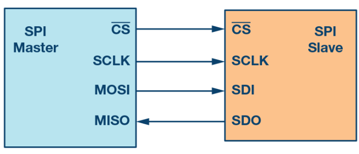
Board SPI Pins
SPI uses the following four wires −
SCK− This is the serial clock driven by the master.MOSI− This is the master output / slave input driven by the master.MISO− This is the master input / slave output driven by the master.SS− This is the slave-selection wire.
SPI Modes of Operation
We have already seen that it is the job of the Master device to generate the clock signal and distribute it to the slave in order to synchronise the data between master and slave. The work of master doesn’t end at generating clock signal at a particular frequency.
In fact, the master and slave have to agree on certain synchronization protocols. For this, two features of the clock i.e. the Clock Polarity (CPOL or CKP) and Clock Phase (CPHA) come in to picture.
Clock Polarity determines the state of the clock. When CPOL is LOW, the clock generated by the Master i.e. SCK is LOW when idle and toggles to HIGH during active state (during a transfer). Similarly, when CPOL is HIGH, SCK is HIGH during idle and LOW during active state.
Clock Phase determines the clock transition i.e. rising (LOW to HIGH) or falling (HIGH to LOW), at which the data is transmitted. When CPHA is 0, the data is transmitted on the rising edge of the clock. Data is transmitted on the falling edge when CPHA is 1.
Depending on the values of Clock Polarity (CPOL) and Clock Phase (CPHA), there are 4 modes of operation of SPI: Modes 0 through 3.
Mode 0: Mode 0 occurs when Clock Polarity is LOW and Clock Phase is 0 (CPOL = 0 and CPHA = 0). During Mode 0, data transmission occurs during rising edge of the clock.
Mode 1: Mode 1 occurs when Clock Polarity is LOW and Clock Phase is 1 (CPOL = 0 and CPHA = 1). During Mode 1, data transmission occurs during falling edge of the clock.
Mode 2: Mode 2 occurs when Clock Polarity is HIGH and Clock Phase is 0 (CPOL = 1 and CPHA = 0). During Mode 2, data transmission occurs during rising edge of the clock.
Mode 3: Mode 3 occurs when Clock Polarity is HIGH and Clock Phase is 1 (CPOL = 1 and CPHA = 1). During Mode 3, data transmission occurs during rising edge of the clock.
For Detailed Explanation Click this link
Video for better understanding
